A One-Page Guide to Fixing Radiated Emissions
Radiated emissions are a measure of how much electronic noise an electronic product emits into its surroundings. The government sets limits on this noise with the goal of regulating the limited electronmagnetic spectrum available to legitimate transmitters - i.e., wireless communications.
That’s a delightful description, but not a particularly useful one. I’m willing to bet that, if you’re reading this page, “radiated emissions” likely means “a test your design is failing”.
Why do you care?
Three reasons:
You can’t sell a product that isn’t in compliance with the regulations. And you’re obviously in this for the money.
You generally can’t find all of your emissions until you’ve started building your electronic product. It is hard - at this point in time, impossible, in my opinion - to predict exactly what will radiate, and why.
You don’t want your cell phone call to 911 to be interrupted by some SDR jockey overclocking his UART. (You’re a clever guy, Ted, but when I want an ambulance, I want an ambulance.)
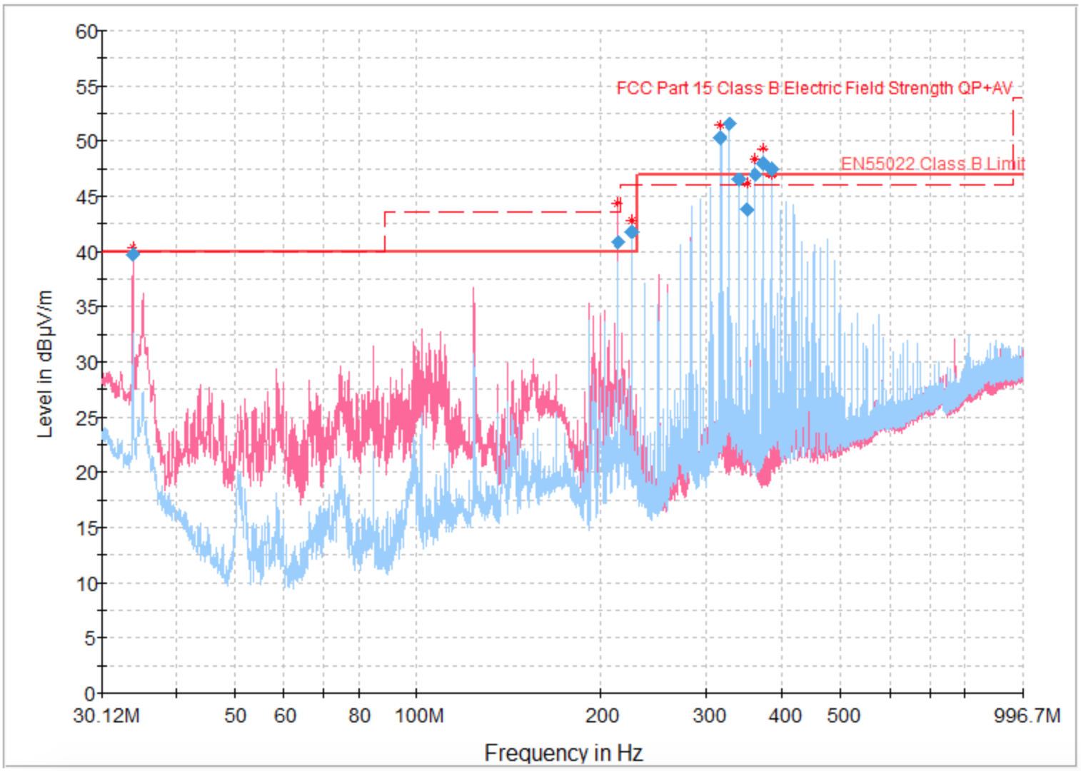
So, let’s focus how you can find and fix what’s causing your circuit to fail. This article is a quick description of how to find noisy, radiating circuits, and how to squash them once you find them. We’re just gonna focus on Class B radiated emissions - 30MHz to 1000MHz - because that’s where most consumer products have problems. We’re also going to treat this mostly in terms of narrowband radiated emissions - things that look like this on a radiated scan:
I’m also kind of assuming that you’ve got a test setup handy, and you need debug steps, not test equipment advice.
Step 1: Find the Aggressor
In test terms, a radiated emissions scan is a test of how many unintended radios you built into your electronic device. Any good radio engineer will tell you there are two parts of an RF design you care about optimizing: the transmitter, and the antenna. Fixing radiated compliance issues is no different - we want to find what’s making the noise (the transmitter), and what’s radiating it (the antenna). The difference here is that we’re trying to actively disrupt both of those components, rather than improve them.
Peak Table + Excel
This is about as easy as it sounds: take your peak table, dump it into an Excel sheet, and divide the peak frequencies by all of your system clock frequencies. The aggressor clock is the one with a lot of integer multiples.
Narrowband radiators tend to be things like clocks or digital signals. Show up on frequency scans as comb frequencies. Remember Fourier: it’s not a square wave, it’s a bunch of sine waves lumped together.
Confirm the Aggressor
Figure out a way to confirm that your suspect signal is the aggressor. This generally means making the signal better or worse on your scan: if your scan results are changing, you know you’ve found your aggressor! Here are a few ways I’ve used to some success:
- Lift or disconnect a pin on the chip that receives that signal.
- Turn off the transmitter for that signal - Hi-Z’ing the signal in SW is great for this. (If you’re running a Linux system, a copy of the
devmembinary and a GPIO reference manual are your best friends here. You can builddevmemas part of BusyBox.) - Is the receiver on a separate PCB? Try disconnecting the PCB. The signal should go away on the scan.
Step 2: Run through the Easy Fixes
A quick aside on measuring radiated emissions: 1-2dB in variation is within the margin of error for a rad scan. You need to change the signal magnitude by at least 3dB to know you’re having an effect. A 6dB improvement in a result is the EMC equivalent of a punch on the nose. A 20dB change is a laser guided bomb.
- Add a series termination. You’re fighting a fundamental battle against Ampere’s Law here. The magnetic field from the aggressor signal is proportional to the current. Decrease the current, and you decrease the field. Decrease the field, and you decrease the emission.
- Decrease the drive strength. This is a variation on the theme of series termination. If your transmitter comes from a big fancy application processor, you likely can adjust the drive strength of the transmitter pin. That
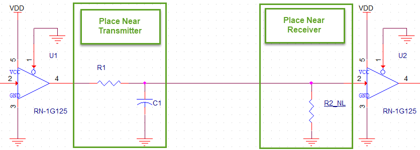
devmemutility, plus a processor reference manual, can allow you to change the drive strength in real time, and watch the aggressor magnitude change on your spectrum analyzer. - Add some basic filtering. If you can’t fix with just a series term, an RC filter help get you the last leg of the way. Choose a C value such that the 3dB frequency formed with your series R is within a few megahertz of your lowest frequency problem radiator. Note: this is where you will start to see tradeoffs against your signal integrity. That’s enough of a topic to merit its own post - for now, I’ll say check your digital signal integrity as well as your radiated performance before declaring victory. See the end of this section for a standard design I use for digital signal paths.
- Go for the bonus filter. Common mode chokes are your best friend when working with high speed differential pairs like Ethernet, PCIe, or HDMI. (As a personal aside: I have no idea how HDMI running at 1080p passes most radiated emission scans. Please email me and explain if you have a good answer.)
Step 3: Try the Hard Stuff.
If you’ve made it this far in the guide, you’ve more than likely got a PCB problem. Congratulations! You’ve won yourself another board spin. Here’s me, crossing my fingers that your project schedule accomodates that.
This is where you have to start demonstrating that you know the aggressor, and how a half-baked fix can demonstrate the potential gains of a board spin. A change that moves your signal by 3dB, poorly executed in rework, will likely have bigger and better effects when built by a PCB house. Be prepared to talk your project manager through lots of high-uncertainty options.
- Meet your new best friend: copper tape. Got a big wire loop somewhere? Try making yourself a nice copper plane for return currents. Don’t forget a layer of Kapton tape - you’ll need it to prevent all the components under the copper tape from shorting out. Solder the tape to GND in as many places as you can at each end. Press the tape as firmly to the board as you can. You want the loop size to be small.
- Mock up shielding. The bonus round of Kapton and copper tape adventures. Think one component is the source of some radiated emissions, but can’t pinpoint where? Use copper tape to put a nice little Faraday cage around it.
- Mock up lower impedance traces. Are you working with shitty, poorly-controlled transmission lines? Twisted pairs might actually have a better impedance profile! Cut the trace as close as you can to the transmitter, solder in a wire, and solder in a ground wire as close as possible to the transmitter wire. Make a tight twisted pair. Solder to the destination. Be very, very careful with your new and delicate test unit. Note that this is a diagnostic tool for showing that your board impedance sucks. It’s not a permanent fix.
- Review your layout. You should have airtight answers to all of these questions before your next board spin:
- Do you know exactly where your return current is going?
- Are your diff pairs matched in length?
- Are your diff pairs matched in phase?
- Is your impedance stackup specified?
- Do you have any data from your board vendor that confirms your impedance stackup?
- Unify your ground plane. You followed the stupid, stupid advice of some vendor datasheet, and split your design into Analog and Digital grounds, didn’t you? Undo this. One ground plane will fix almost all unfixable emissions problems. Improve your routing breakout to compensate - keep the analog signals far, far away from that noisy digital switching. Get rid of any slots or breaks in the ground plane. Don’t route high speed signals through connector footprints that they don’t connect to. The signal will find some way to radiate through it.
- Take a look at your connectors. A 0.1" header will sing like a choir if carrying high speed signals. I can nearly guarantee that any signal over 3MHz will show up on a radiated scan if it goes across a pin header connector. If you absolutely must run your high speed signal accross a connector to another board, use something designed for high speed signals: a PCIe connector, a mezzanine connector, or other impedance-controlled interconnect. Need a cable, too? Consider a flatflex cable for lower speed stuff, or better - a flex printed circuit, which you can impedance control.
- Get a metal enclosure. Plastic is as transparent to radio energy as it is irresistible to industrial designers. If you can figure out a way to put your product inside a big metal can, you now have a Faraday cage to help alleviate the strain of radiated emissions. Are you in a metal can, but seeing emissions anyway? Try improving the connection to that can to earth ground.
- Consider taking your project manager drinking. I did say we’re at the point we’re trying the hard stuff.
Good luck - I hope you ship a million of these things.