bFunc - Project Journal - Week Three
Here’s the build log for week three of development for the open source function generator I’m trying to prototype and build in time for for OSHWA 2020.
Each day’s entry represents an hour’s work per day - the hour before I leave for my job every weekday morning.
This is my log for the week ending Feb 21, 2020. (Well, actually, Feb 22. Make-up workday.) You can read up on the first week’s work here, and the second week’s work here
Feb 22 2020
- Doing a quick hour’s work on Saturday morning as a make-up for missing Friday.
- Working on a nice way to both store the DDS chip state in a single block of memory, and access it.
- Friend Jason suggested a means of using a struct pointer to access the underlying uint8_t array:
uint8_t data[4];
struct ad9837_ctrl_reg *dds_control = data;
InitCtrlAD9837(dds_control);
- I will admit that it’s elegant, but also makes me anxious - in no small part because I feel it violates Kernighan’s law. (I am definitely not learned enough in C to debug this super effectively.) Additionally, the compiler un-shyly throws a warning here (in typically un-shy compiler fashion):
Src/main.c:160:41: warning: initialization of 'struct ad9837_ctrl_reg *' from incompatible pointer type 'uint8_t *' {aka 'unsigned char *'} [-Wincompatible-pointer-types]

 160 |  struct ad9837_ctrl_reg *dds_control = data;
- Also kind of wondering if this isn’t overloading the function call a bit.
- The dds_control struct is really just a nice way of letting a human understand the bit setting/clearing quickly and easily.
- The actual hardware (and the HAL) expects a nice array of uint8_t’s to write out of the peripheral onto the SPI bus.
- One possible solution - pass a pointer to data to each function (e.g. StartOutput(uint8_t *data);), and then point to it like it’s a struct of dds_control
- Allows you to only pass one argument, but still gives you the ability to set/clear bits in a nice human readable way
Feb 21 2020
- No progress on code today - had a very human bout of insomnia that I compensated for by shutting off my alarm, sleeping in, and being late to work. (Oops.)
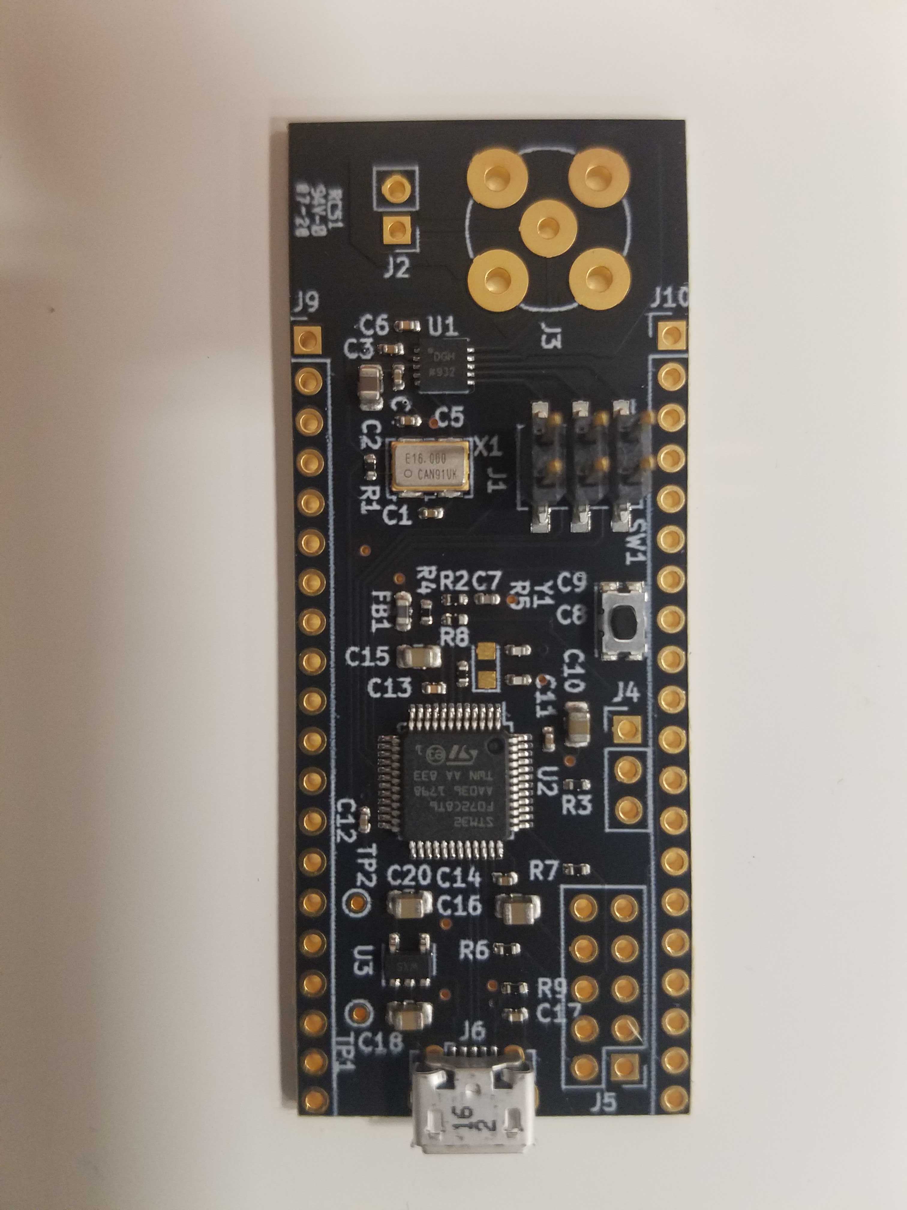
- Got an email from CircuitHub - boards have been assembled, and are en route! They should be here Monday!! Here’s a picture!!!

Feb 20 2020
- Added a nice little state machine that just toggles between a sine output and no output.
- Also wrote a bit of next state logic that can be expanded out into a Mealy machine once we get some more possible inputs.
- Starting to write a SetWaveformMode() function - going to need to stash another variable here somewhere to store what the current output state is.
- Need a variable to store that, because we need to know if the DAC is running or not.
- Created a little struct that’s bit-packed to map to the DDS’s control register.
- I need to map this into a uint8_t array to write out to SPI now. How do I do that?
- It’d be nice to use gdb to examine how the struct is packed so I know how to bit shift it into the single byte SPI char array.
- I can
print dds_controlin gdb, and I canx &dds_controlto see the address, but I don’t know a way to see the underlying bytes thatdds_controlis stored in.
Feb 19 2020
- Rewrote the reset/init code of the AD9837
- Instead of a hard-coded 250Hz wave, it now has separate function calls for starting output, stopping output, and setting the Freq0 register value
- Note: will need to update the Freq0 register settings so as not to overwrite other values in that register
- Will be needing some sort of mild state machine to manage waveforms and switching logic soon.
- Will also need (or at least would really like) some form of UI so I don’t need to re-flash the board whenever I want to make a dumb code change.
Feb 18 2020
- After some twiddling and breadboard setup - it’s working! At least, a little bit.
- Used ADI App Note AN-1070 to get a jumpstart on configuring registers for the AD9837. Took a bit of futzing around.
- Originally, I noted that the output frequency was very high - way higher than I’d set it. Some digging revealed a set of bits that were reversed. Fixing this cleared things up in a jiffy.
- Still not 100% perfect - I used the App note values, which assumed a 25MHz reference clock instead of the 16MHz I’m using on this Minigen eval kit from Sparkfun. That’s just math, though. Progress!
- Also - this value updates fast in the ADC.
Feb 17 2020
- Technically not working today - I took a long weekend trip to NH to go skiing. No real progress for Monday.
- …though I did get an email from the folks at CircuitHub, who kindly flagged my order as having a faulty hanging net. Whoops. I rerouted the power plane somewhere else, and forgot to clear one of my dangling traces. It shouldn’t have a negative effect on the electronics - it’s just embarrassing.
Feb 14 2020 (Later in the Day)
- Said “Fuck it”, whipped out my credit card, and ordered 10 assembled boards from CircuitHub. Total cost: just over $1300.
- I had to compromise on quantity, but I will at least have HW to hand out to a few people at OSHWA. (Not very many pieces, but enough to say I did it, dammit!)
- This turned out to be an excellent decision. At some point over the weekend, I got an email from PCBWay saying that lead times for all PCB and assembly orders was now being pushed out to 60-75 days due to the coronavirus outbreak. Yikes. Coronavirus is already eating up my work life. Now it’s taking aim at my personal projects too!