bFunc - Project Journal - Week One (and a Half)
Here’s what the first week of development looks like to build an open source function generator in time for for OSHWA 2020. Each day’s entry represents an hour’s work per day - the hour before I leave for my job every morning, to be precise.
Feb 7 2020
- Initial placement underway!
- Like the cross-association between layout and schematics in KiCAD.
- Highlight a component in EESchema, and it will be highlighted/selected in PCBNew
- Kind of hard to do on my Macbook. I wish I had a second monitor.
- Wish there was a way to select a cmpt, then hit a button that was like “Jump to Layout Editor” - I always seem to select a component in EESchema, then click into PCBNew, and find it’s been de-highlighted.
- Deleted the secondary LDO
- Not really using any analog functions of my MCU
- Could use it as aux power to the DDS, but that’d mean a long power route somewhere that I don’t really want to futz with.
- Starting to think about test point placement
- Kerry Scharfglass’s Hackaday video got me thinking about testpoints = fixtures = time saved
- Hi Kerry! Thanks for answering my email.
Feb 6 2020
- Make LFCSP-10 footprint for AD9837
- No need! I was searching for the wrong footprint in the default library. Looking for LFCSP-WD package found it. It was already there! And a check in the footprint editor showed the dimensions matched.
- Finish assigning footprints
- This is more nerve-racking than I expected. Constant thought: “What if I fuck one up?” Instant empathy for team of PCB designers at work.
- SeikoEpson - your recommended footprint pattern for SG5032 oscillators calls out the wrong part number! WHY!!!
- Find the right footprint for the crystal (not the oscillator)
Feb 5 2020
- Replaced LDOs with MIC5504 (much cheaper!)
- Added missing power net for 3.3V rail to DDS oscillator
- Assign RefDes’es
- Done! Easy!
- Make layout floorplan!!
- Assign footprints
- Wow, this takes a long time, and is anxiety ridden.
- Added breadboard headers for mounting (that’s the whole point of this fucking thing!!)
- Would make a whole lot more sense if they connected to something though
Feb 4 2020
- Broke SCH into hierarchical components. Never done a design this way before - we’ll see how this goes!
- Implemented STM32F072C8T7 Reference Design
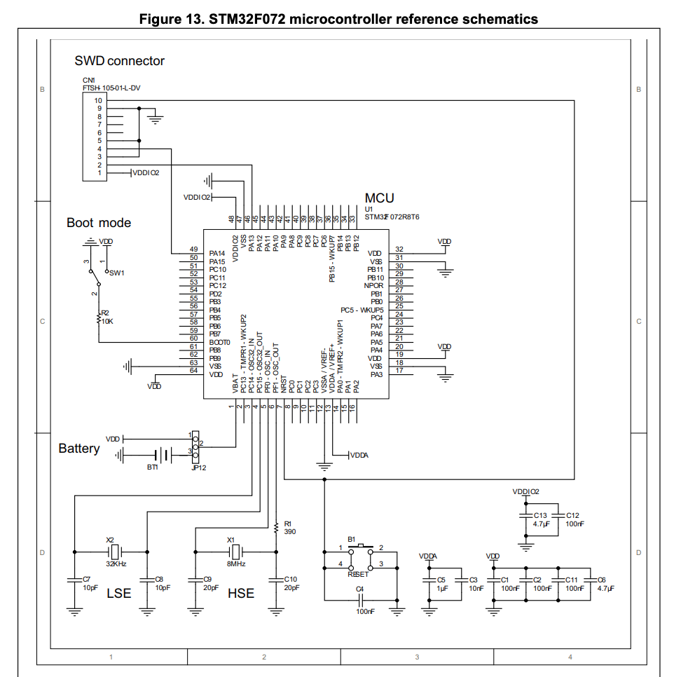
Add TVS for USB- I didn’t do this, and may end up regretting it. Note to self - buy a ground strap.
- Add JTAG connector for MCU!
- Done - went with SWD connection. Compatible with ST-Link, or that Segger I have kicking around in my box of random debugger crap.
Feb 3 2020
- Not a whole lot of sch work, but a lot of questioning my Arch choices.
- Might STM32 be a better choice?
- https://www.st.com/en/microcontrollers-microprocessors/stm32f0x2.html
- STM32F072C8T7
- Datasheet https://www.mouser.com/datasheet/2/389/stm32f072c8-956183.pdf
- Supports Mac toolchain (AVR does not)
- Familiar debug protocol (SWD)
- Just about identical pricing ($2.75 for 10)
- STM32 HW Quickstart Guide (Includes HW Reference Design) - https://www.st.com/content/ccc/resource/technical/document/application_note/c9/19/d7/b8/6b/0e/4c/d3/DM00051986.pdf/files/DM00051986.pdf/jcr:content/translations/en.DM00051986.pdf
Jan 31 2020
- Make symbol for AD9837
- This is easy, and pretty intuitive
- The symbols are the reverse of what I’m used to (orcad) - bubble is the connection point for the wire, not for the symbol box
- I like that you can automagically include the datasheet link and part information
- Also really enjoying the hot keying setup - just hit a button and you bring up a new dialog
- Also - how do you make the interior of the SCH symbol yellow like everything else?
- Start reference design of AD9837
- Issue number 1: what’s the primary power source of this thing?
- Lots of jumper options for selecting power into the device
- Do I gather from the reference design that the AD9837 is supposed to be powered by its own POL, and everything else has a separate POL? If so, I’ll definitely be finding a cheaper LDO.
- Packaged oscillators. Convenience = yay! Price = woof. $1.10 per piece.
- Hierarchical design!
- That’s very cool, and a really different design paradigm than I’m used to.
- See a lot of advantages to it - easily replicate circuit “chunks”
- Is it as easy to do in layout as it is in SCH? Do you get layout rooms by default as well?
Jan 30 2020
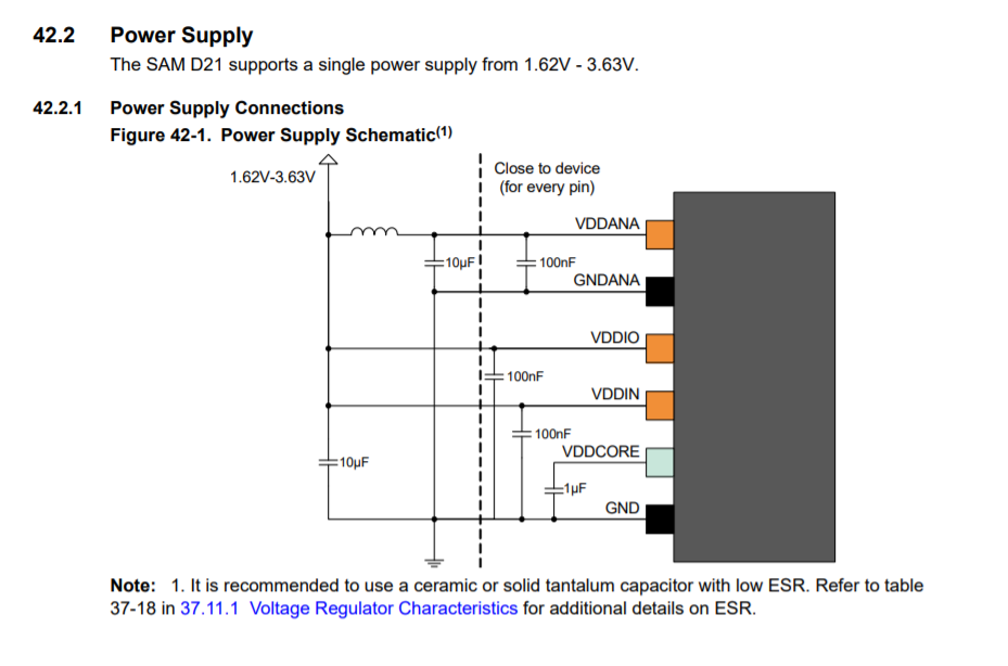
- Start SCH capture of ATSAMD21 MCU
- Use Datasheet Section 42 (SCH Checklist) as guideline for SCH capture
- Note to MFGs: this is a great way to get HW engineers to use your parts
- It’s also a shitload cheaper and more scalable than hiring a bunch of FAEs - paper scales, people don’t!
- Have a step-by-step guide saying “This is how to implement this thing in HW”
- We’re typically some combination of time-crunched, and lazy
- Brilliant!
- http://ww1.microchip.com/downloads/en/DeviceDoc/SAMD21-Family-DataSheet-DS40001882D.pdf
- Use Datasheet Section 42 (SCH Checklist) as guideline for SCH capture
- Need to Find 5.0V -> 3.3V LDO
- Added NCV8114ASN330T1G from On Semi (was in KiCAD’s design library)
- Could probably find something cheaper though
Jan 29 2020
Still mostly parts research at this point.
- ATSAMD21
- Only capable of 3.3V IO voltages, so that kind of dictates what everything else must run at.
- AD9837
- Voltage out only - no need for 200 ohm resistor to terminate current driver.
- No comparator output - square wave achieved by driving MSB of phase accumulator at the VOUT pin.