bFunc - Project Journal - May 3 2020
Here’s this week’s development updates for bFunc, the open source function generator I’m developing to sell. Each day’s entry represents an hour’s work - the hour before I start work on my real job every weekday morning.
If you’d like to buy a board to try, you can purchase one over on Gumroad!
The design doc for this project is available if you’re into design documents/philosophy.
All of my hardware and software source files are on GitHub. Check ‘em out!
May 3, 2020
- Set up a Gumroad Page - I’m officially selling bFunc, through an actual web store!
- If you’d like to buy a board, I have about 10 left.
May 1, 2020
- Looking at some PGA chips
- AD603 (expensive!!)
- PGA113 (cheap!!)
April 30, 2020
- Could we make do with any cheaper opamps in the system?
- A little analysis suggests that Yes, indeed we could.
- There are cheaper opamps for the diff to single ended stage - they just run at lower voltages.
- Even adding two cheap LDOs just to step +/-12V down to +/-5V would be a huge improvement
- TI’s LMH6642 would likely be a decent candidate https://www.ti.com/product/LMH6642
- Similar performance over same frequency range
- Less than half the price of the AD8065 (but also half the voltage range)
- Also, since I haven’t slept much and I’m a little braindead - let’s test the oscillator!I
- Soldered up one of the Horowitz El Cheapo special probes to the oscillator output.
- I didn’t include testpoints to solder a probe on to, so I scraped back some soldermask and soldered to the trace between oscillator and DDS chip.
- Lots of time spent testing whether I was connected to the right trace with a scope.
- Long story short - during this test setup process, I found a bug! I didn’t tie the oscillator ground to the board ground. How dumb. Both these oversights will definitely be fixed in the next rev.
- Learned some cool stuff about oscillators in the meantime.
- For one thing: here’s why you want to give your test equipment a few minutes to warm up. The frequency trend is a straight upward slope for about 5 minutes after USB power is applied.
- It doesn’t really settle into a predictable normal distribution for a few more minutes after that.
- However, after about 10-15 minutes of being on, the oscillator stabilizes, and the frequency binning gets more uniform.
April 28, 2020
- Alright! Next design starts… NOW.
- I’m feeling pretty good about the firmware of my current design.
- I’m not so comfortable with where the analog output stage is at.
- No buffering.
- No proper termination.
- No antialiasing.
- Three main areas I want to focus on:
- Output Driver + DC Offset Control
- Differential to single end converter
- Antialiasing filter
- Output Driver + DC Offset
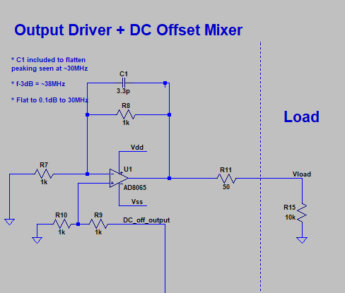
- This is a pretty straightforward inverting buffer based on AD8065 opamp
- Unity gain stable
- Wide bandwidth - GBP at about 150MHz
- Rail-to-rail drive - can push/pull about 30mA
- Not cheap - $3.71 in single quantities, $1.80 at 3k quantitiesI
- Originally chose very high resistance values - 20k and higher
- Simulations showed that this would limit bandwidth pretty substantially. A quick check of the AD8065 datasheet confirms
- Dropping resistor values to 1k made a huge difference
- Moved 3dB freq out from ~1MHz to ~35MHz
- Added a little feedback cap to cut down on some peaking observed around 30MHz (Input is grounded in picture below because I was simulating a prior stage)
- Output is, as it should have been from the start - 50 ohm series terminated
- This is a pretty straightforward inverting buffer based on AD8065 opamp

- DC Offset + Output
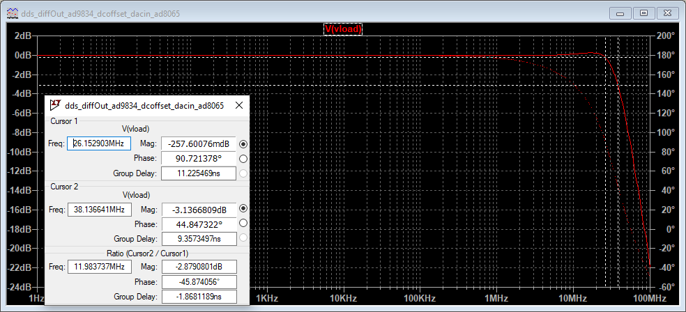
- Frequency response is flat +/-0.25dB out to 25MHz
- Cursor 1 shows the point at which it starts to deviate from 0.25dB flatness area (26MHz)Cursor 2 shows the -3dB frequency (38MHz)

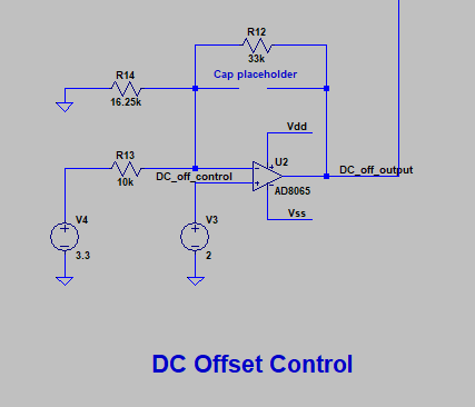
- DC Offset Control
- Inspired by a few TI app notes on unipolar-to-bipolar conversion circuits
- http://www.ti.com/lit/an/sbaa343/sbaa343.pdf?ts=1588073331377
- http://www.ti.com/lit/ug/slau525/slau525.pdf
- http://www.ti.com/lit/ug/tidu974/tidu974.pdf
- This circuit followed the design steps in that first TI app note, SBAA343
- Plug in your DAC output range, and reference voltage, and your resistor values are just plug-and-chug.
- AD8065 is probably not the right choice of opamp here - it’s wildly overspecified.
- This stage is gonna be driven by a DAC output at pretty low frequency - 500kHz bandwidth or less.
- Can likely get away with a cheaper opamp - I just haven’t done the work to find it yet.
- Cap placeholder is there for the same reason as in the output buffer - it helps cut down on a bit of the ringing/transient overshoot in fast DC step transitions
- Inspired by a few TI app notes on unipolar-to-bipolar conversion circuits

- Antialiasing Filter
- I’d really love to have a way to capture a scope waveform of my existing system with the AD9837, and then feed that waveform into LTSpice as a simulation input.
- My cheapo Rigol scope doesn’t have the capability to do this - or if it does, I don’t know how to access it.
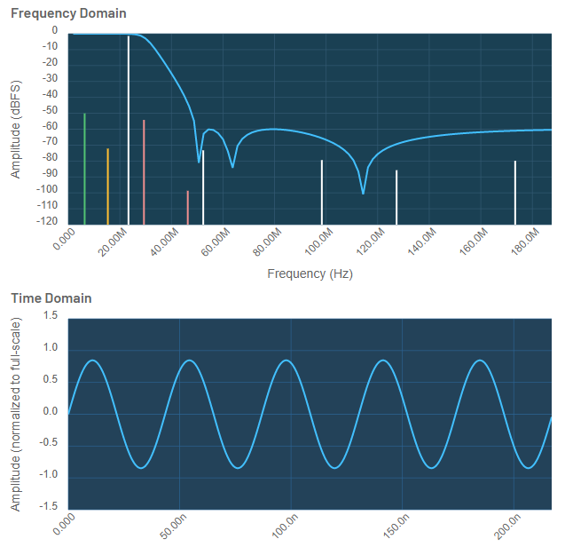
- ADI doesn’t have the answer to that question, but what they do have is pretty cool - the ADIsim DDS webpage.
- Allows you to select your DDS chip, your output signals, and whether or not you want an external antialiasing filter. VERY cool, and worth playing around with.
- Below shows the output of a DDS chip running at 23MHz output, after being filtered with a 7th order inverse Chebyshev lowpass filter.
