The One Page Guide to Digital Signal Integrity
I’m boggled by the number of people I interview that don’t know the basics of digital signal integrity. Given that, I’m going to be the change, and write down everything I like to ask EE interview candidates about digital signals.
I wrote it as list first, with answers discussed later - feel free to try and quiz yourself, or just scroll straight down to the answers.
- Setup/Hold
- Where, on an electrical waveform, would you measure for setup/hold?
- Where, on a circuit board, would you measure for them?
- How can you use these parameters to figure out the maximum speed of an interface?
- Rise time/fall time
- How do you measure rise and fall time?
- Why do you care about it?
- Is monotonicity of a rising edge a requirement?
- Overshoot/Undershoot
- Why do you care about it?
- When is it a problem?
- How do you fix it?
- Terminations
- What kind of terminations are there? Can you show me a few examples?
- What’s the point of a termination?
- More Advanced
- What other kinds of options do you have to modify a transmitted digital signal, besides termination?
- Is there ever a good reason to degrade your signal integrity?
- How do you determine which traces are long enough to treat as transmission lines?
Note: I typically won’t beat up on you too hard beyond setup/hold if you’re not a digital EE candidate. Opinions on this vary.
Setup/Hold
This is always the first place to start when it comes to signal integrity. These three questions give me the most bang for the buck when talking to a candidate:
- Where, on an electrical waveform, would you measure for setup/hold?
- Where, on a circuit board, would you measure for setup and hold?
- How do you use this to figure out the maximum speed of an interface?
It’s basic stuff, but it susses out very quickly that the person on the other side of the table has actually worked hands-on with digital circuits.
Where, on an electrical waveform, would you measure for setup/hold?
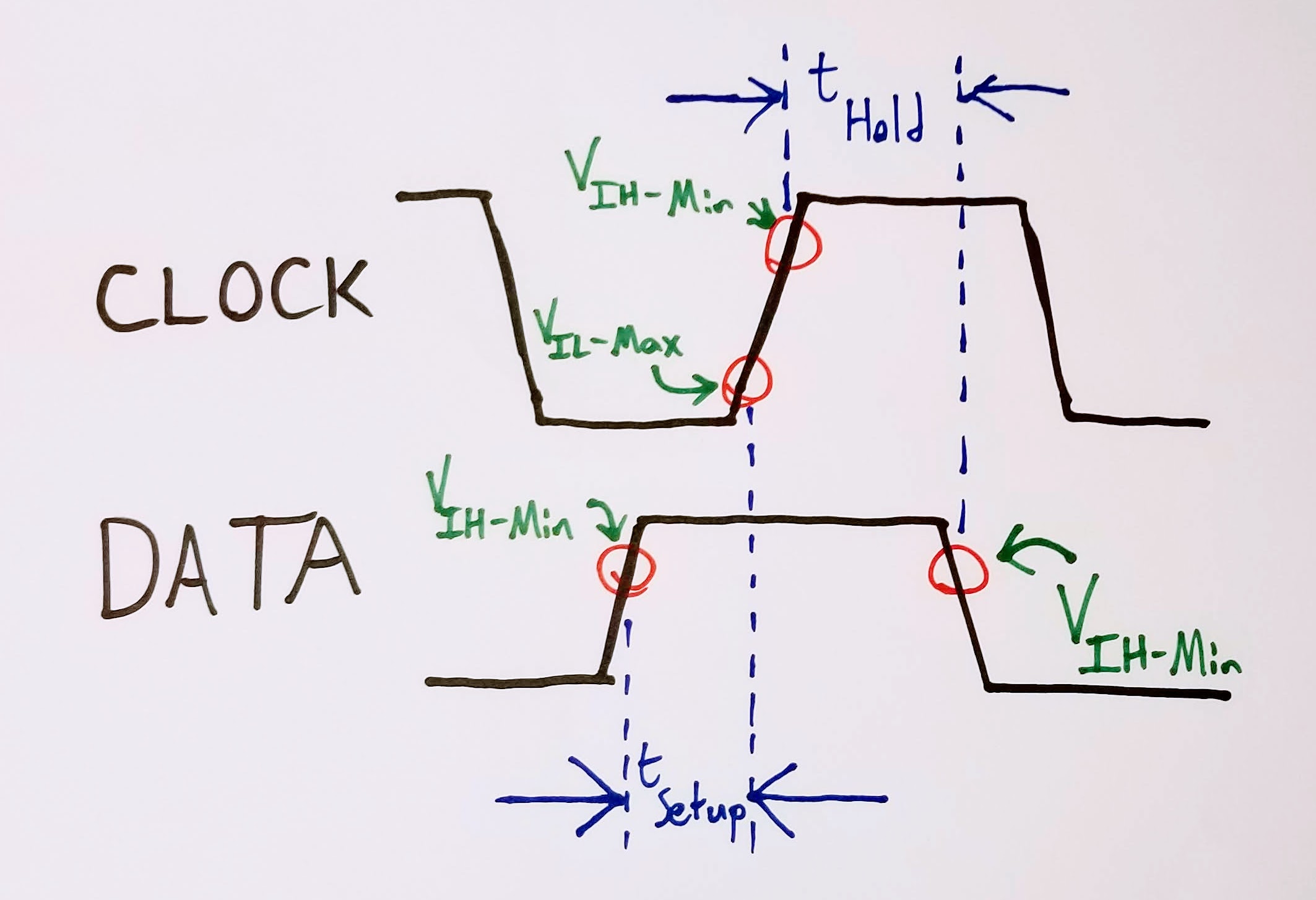
Number One is an easy question to answer with a sheet of paper - ideally, the candidate draws a clock waveform, a data waveform, and then labels a few key points:
Where would you measure setup/hold on a circuit board?
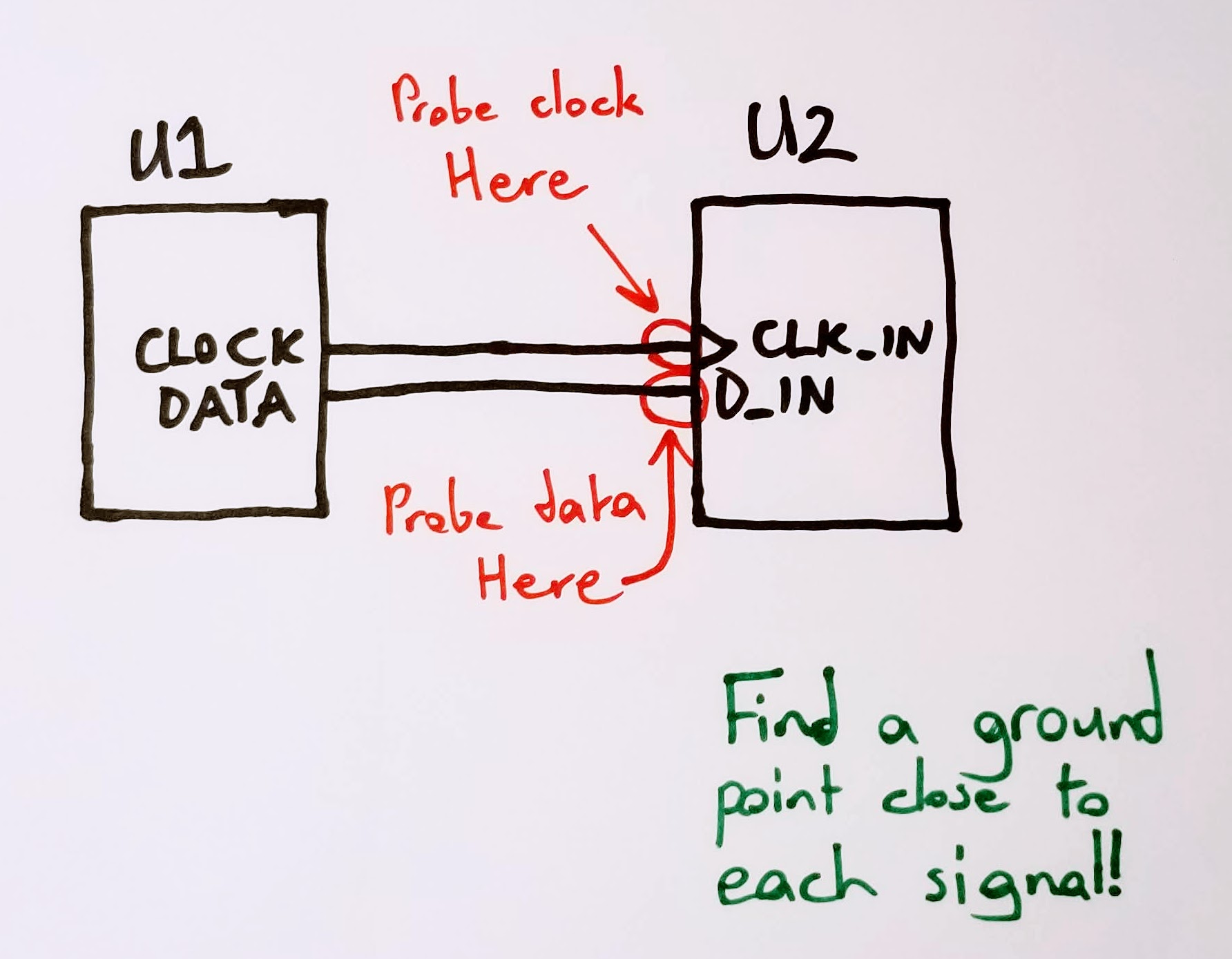
Question Two helps show whether you understand that your oscilloscope has an impedance. It also shows whether you understand how to minimize that impedance. Ideally, you can translate the first question into a simple, block diagram topology that the candidate can use to indicate the right place to probe. It’s also a great time to ask about grounding, and how that can change probe impedance.
How can you use all of this information to figure out the maximum speed of an interface?
Question Three is a bit academic, and, arguably, one of those questions that rewards those who remember trivia from introductory digital design classes. Generally, though, most people don’t remember that level of minutiae, so it serves as a nice window into their thought process. Most people need a little prodding into how to add up all of the time intervals, but most eventually settle on to the right answer: \[f_{max} = \frac{1}{t_{hold} + t_{setup}}\]
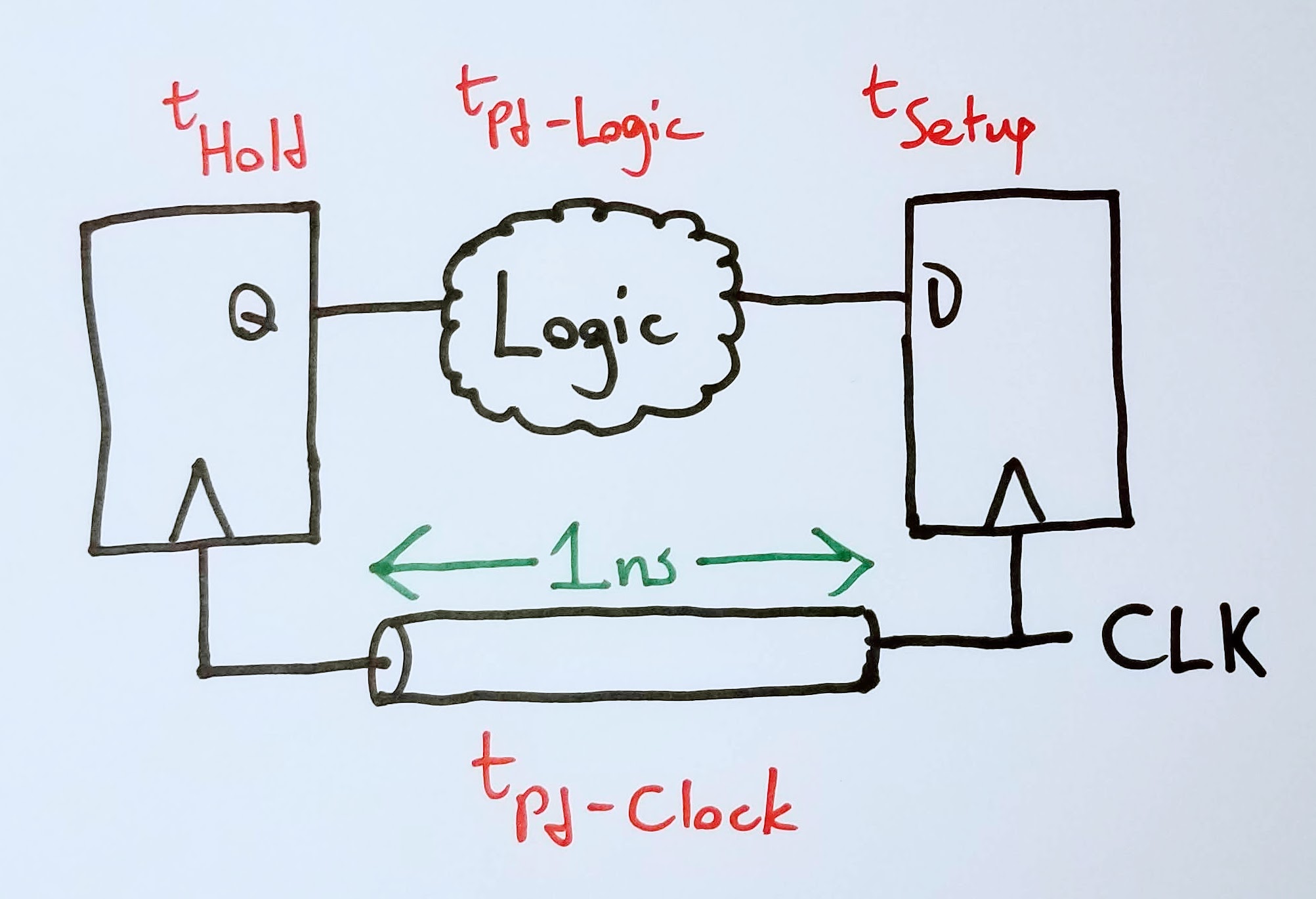
You can make Question Three a bit spicier by asking it as a system of two D flops with some combinatorial logic between the two:
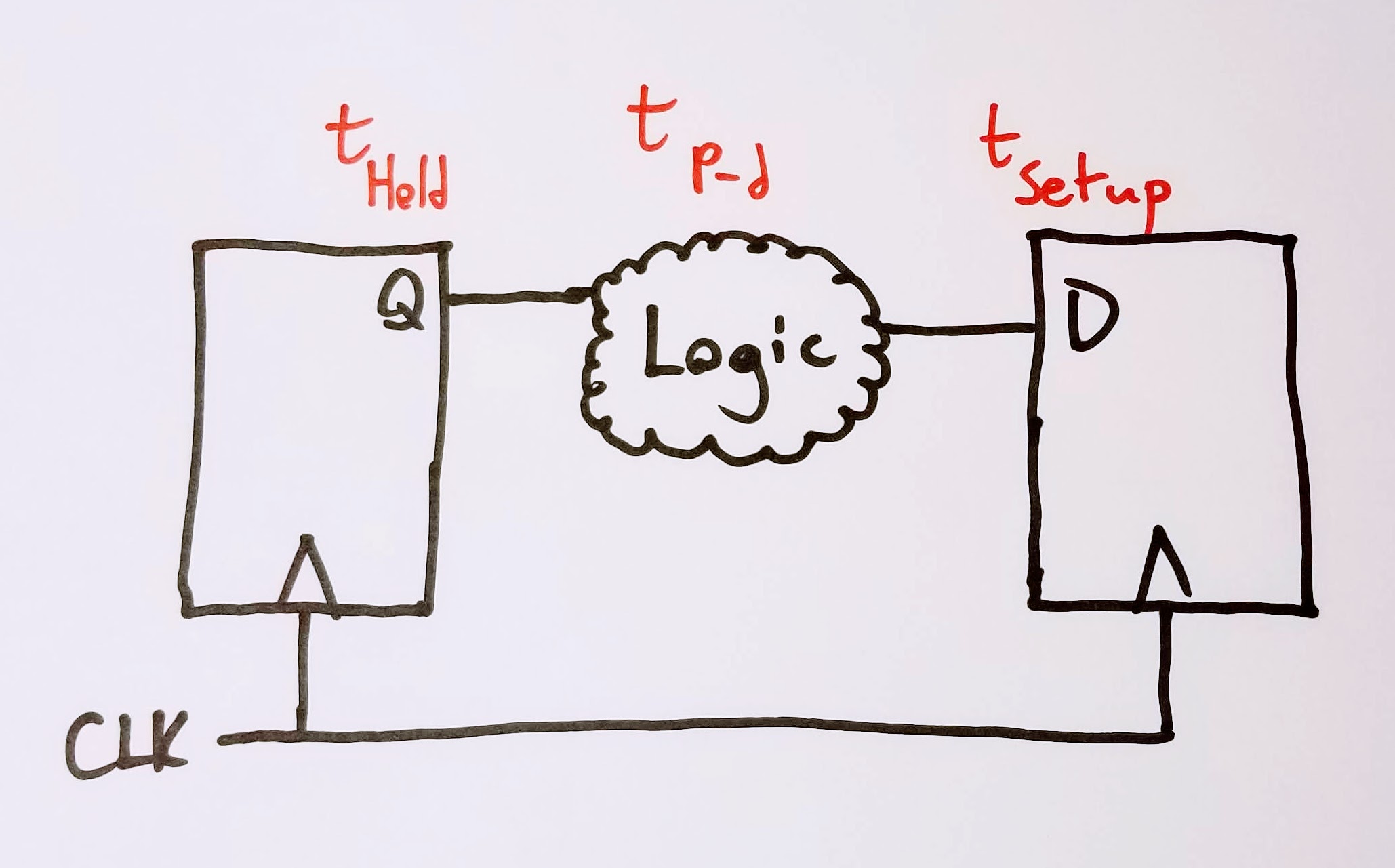
Which makes you have to account for the propagation delay of the logic: \[f_{max} = \frac{1}{t_{hold} + t_{setup} + t_{Pd-logic}}\]
You can get more fun still by adding a clock transmission line into the mix…
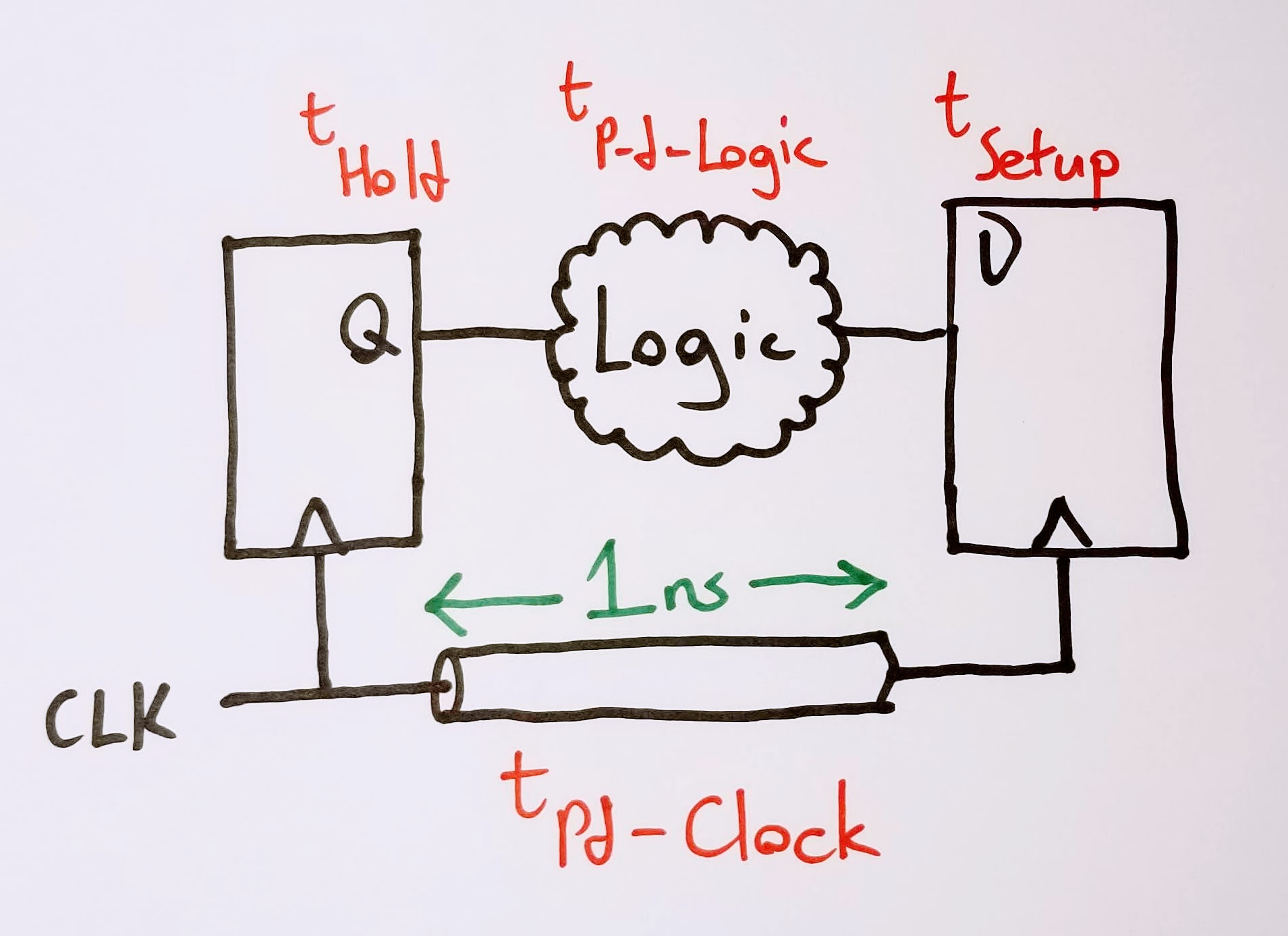
…and asking how the propagation delay of the clock affects the max speed of that interface: \[f_{max} = \frac{1}{t_{hold} + t_{setup} + t_{Pd-logic} - t_{Pd-clock}}\]
Note that the position of the clock launch is important here. \(t_{Pd-clock}\) is negative, because it allows more time for the signal to propagate through the combinatorial logic. Shifting the launch position to the second flop has the opposite effect:
This interface has to run slower, because the first flop needs time to setup its newest output into the combinatorial logic, and then that output to propagate through to the second flop. Thus: \[f_{max} = \frac{1}{t_{hold} + t_{setup} + t_{Pd-logic} + t_{Pd-clock}}\]
Rise Time/Fall Time (a.k.a. Slew Rate)
Rise and fall time is a great stepping stone from setup and hold, because it starts to probe into frequency effects that are more analog than digital.
- How do you measure rise and fall time?
- Why do you care about it?
- Is monotonicity of a rising edge a requirement?
How do you measure rise and fall time?
Question One should be a quick annotation on the clock and data diagrams sketched earlier:
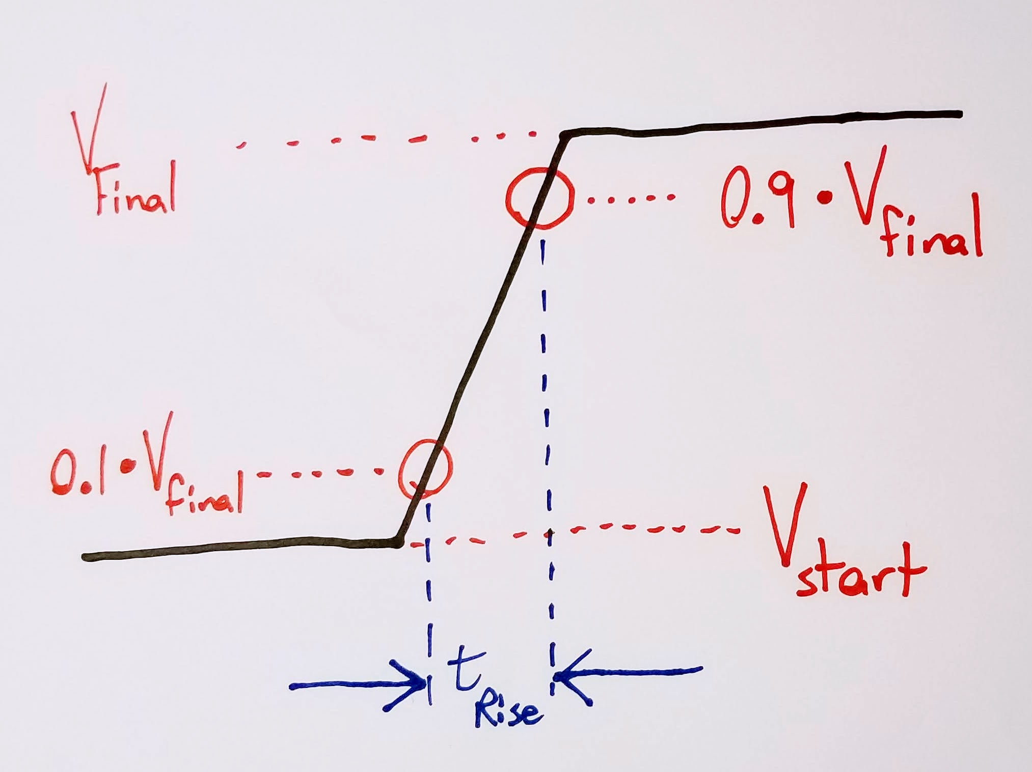
I generally use the 10-90 rule for measuring rise/fall: 10% of starting value to 90% of final value. There’s no 100% right answer for all scenarios; it can vary from chip to chip and from vendor to vendor.
Why do you care about rise/fall time?
I use Question Two to understand how well the candidate gets that the edges are the “analog portion” of the signal - i.e., where you’re going to see the most non-digital effects (and the most problems created for the digital circuits themselves). This question usually leads organically into topics like terminations, discussions of monotonicity, or emissions.
Are all rising/falling edges required to be monotonic?
As with most engineering questions: it depends.
For synchronous digital I/O - no, there’s no reason your signal needs a monotonic edge.
For clocks, resets, and other asynchronous I/O - yes, you’ll need a monotonic edge. This eliminates the possibility of double latching, which can create serious problems in your system.
At some point in this discussion, you’ll get bonus points if you bring up the concept of systems that are sensitive to edge slew rate. (Questions Two or Three tend to spur those conversations.) Many high speed digital systems (particularly DRAM) implement derating based on clock slew rate. Many processor IOs are also sensitive to slow slew rates - you’ll require some sort of Schmitt input to interface a slow transitioning IO to a pin. (Luckily for you, Schmitt input is an option on many modern SoCs!)
Overshoot/Undershoot
After setup/hold and slew rate, these questions tend to be a bit of an afterthought.
Why do you care about over/undershoot?
You care about overshoot and undershoot because it can break your chip. Simple as that.
When is it a problem?
It’s a problem when the overshoot or undershoot exceeds the rated input limit of the receiving chip. Bonus points if you go into a little detail about clamping diodes, which are a very common method of protecting digital inputs.
How do you fix it?
You fix it by changing some characteristic of the transmission network:
- Injecting less energy into the transmission line: this is typically the easier and preferable route. Add termination, reduce drive strength, modify emphasis settings, etc.
- Reducing the inductance of the transmission line: this is a rougher road, because it generally means an oversight in your original layout - something like a missing stitching via during a ground plane transition, or a connector that has too big of a service loop.
Terminations
What kind of terminations are there? Can you show me?
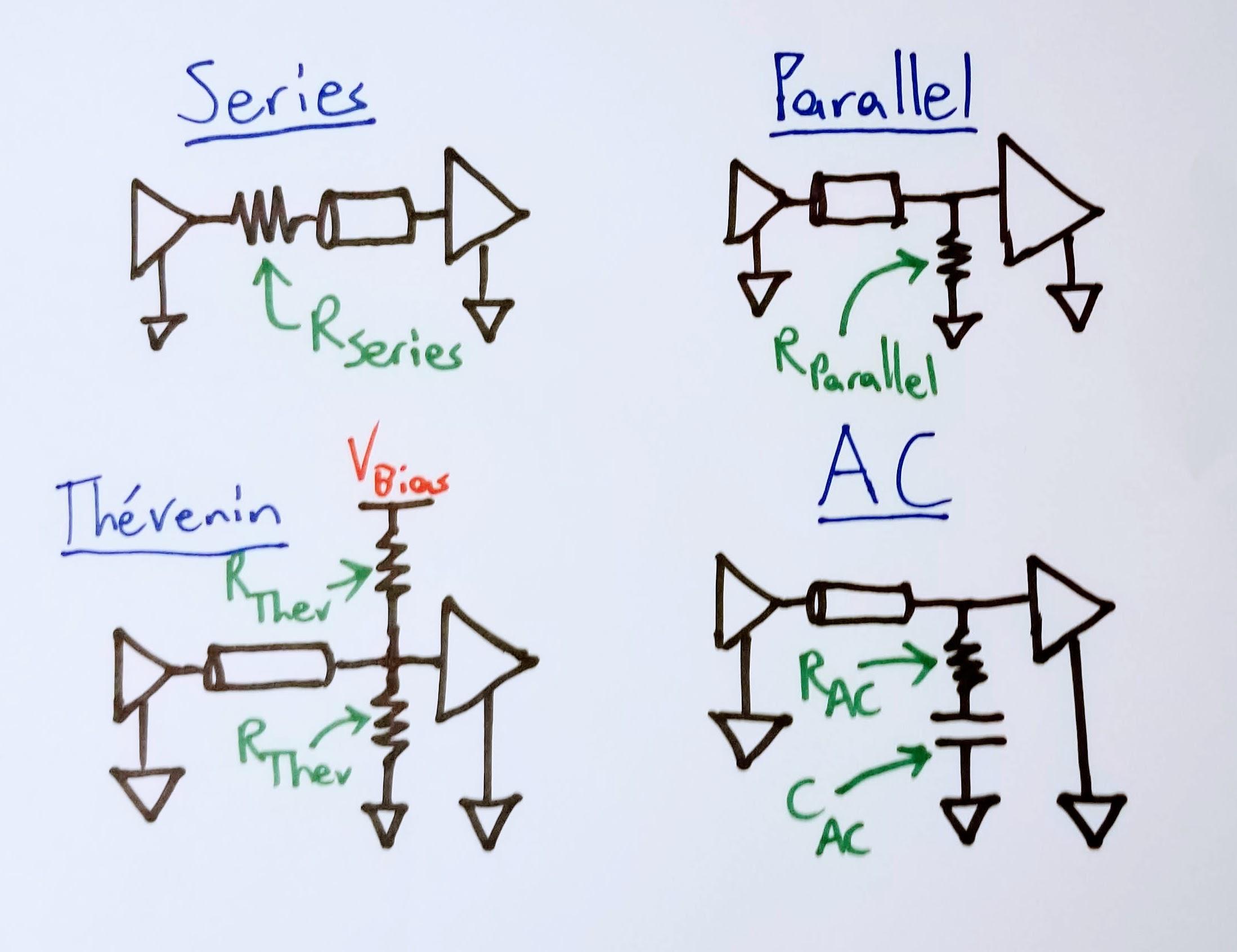
There are really four termination topologies that you care about:
- Series
- Parallel
- Thevenin
- AC
And each one is a real quick sketch, so why not doodle them out?
What’s the point of a termination?
Plenty of answers, but the most succinct answer I can think of is: compensating for reactive components in a digital transmission line.
That can break down into a lot of more specific answers that I’ll take in lieu of a top-level catch-all:
- Stopping reflections
- Stopping ringing or other oscillations
- Slowing down the rising edge of a signal
- Making clock edges monotonic
More Advanced Stuff
I like to ask these if my interview is going well, and the interviewee blew through earlier questions more quickly than expected.
What other kinds of options do you have to modify a transmitted digital signal, besides termination?
This is a pretty broad probe to see how far the candidate has gone down the rabbit hole of chip-level physical layer controls. Not really a right-or-wrong question - just getting a sense of the breadth of chip technologies they’ve worked with.
I’m looking for answers along the lines of the following grab bag of tricks:
- Driver impedance
- Current drive strength
- Slew rate control
- Preemphasis/deemphasis
- Equalization
Are there ever times that you would want to degrade your SI?
I’d expect an experienced candidate to answer: “Of course!” Fast edges mean high energy signals, and high energy signals can radiate with the proper length of etch/wire serving as an antenna. That radiation can show up in an emissions test chamber! Worse - it can require a board spin to tame it!
This generally loops back to adding some sort of termination or drive strength control. Every now and again I’ll talk with someone about HDMI, or PCIe cards, and we’ll have a good stitch’n’bitch about common mode noise. (Recommend me your favorite brand of high speed common mode choke, and you’ll be a strong “Hire” in my book. I’m partial to Murata DLM series, myself.)
How do you determine which traces are long enough to treat as transmission lines? How can you predict emissions performance from this info?
This is my personal shibboleth to find fellow fans of Howard Johnson’s High Speed Digital Design. Johnson’s got two great rule of thumb equations in chapter one that I use all the time.
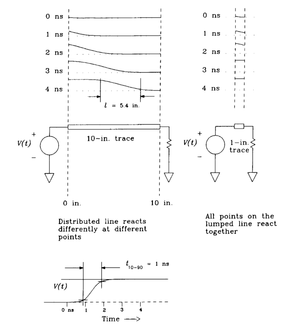
The first equation is the propagation wavelength, which compares the length of the rise/fall time to the length of the trace on which it’s traveling: \[l = \frac{T_{r}}{D}\]
Where \(T_{r}\) is the rise time of the edge (in picoseconds) and \(D\) is the trace’s propagation delay (in picoseconds per inch). Johnson refers to this distance as the discriminator between lumped vs. distributed circuits. It’s a rough rule of thumb as to how far a signal has to travel before having to worry about transmission effects like reflections or ringing. According to Johnson, a signal with propagation wavelength \(l\) traveling down a trace \(l/6\) (or less) won’t exhibit any transmission line effects, and won’t require a termination.
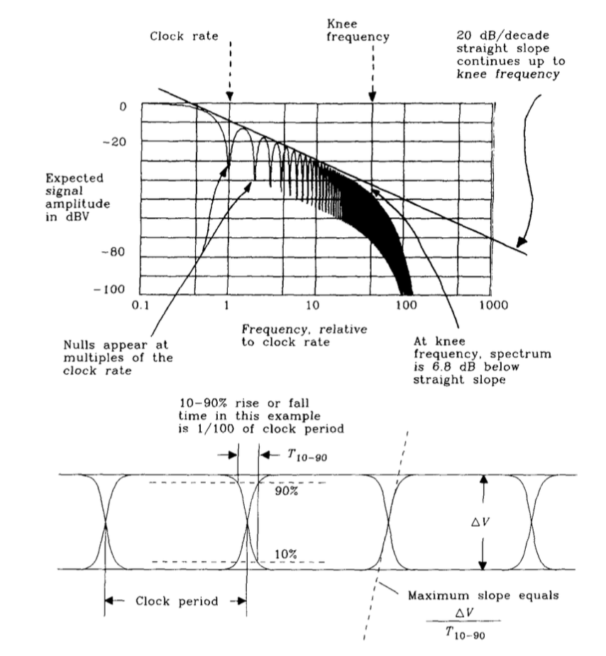
The second equation is for the knee frequency: \[F_{knee} = \frac{1}{2T_{r}}\]
where \(T_{r}\) is the 10-90% rise time of a digital signal.
I love asking about this particular point from Johnson because I found it so enlightening when I first learned about it. The fundamental insight is that it’s the edges of a digital signal that contain the bulk of the energy in them. It also gives you a practical idea of the highest component frequencies in your digital signal. (Yeah, yeah - Fourier says there are infinite sinusoidal components, but that’s math, and math describes real life - not the other way around.)
This is super useful in determining which signals you want to run across connectors or lengths of wire, because it gives you an idea of what frequencies are present in that signal. More importantly, it gives you an idea of which of those signals might radiate. You might get unlucky and send a harmonic over a cable that happens to be \(\lambda/4\) long. If so, congratulations! You’ve just made a radio! You’ll find it in a radiated emisssions chamber.
Further Reading
Most of what I ask is elementary digital design stuff. The textbook I learned most of that out of is Wakerly’s Digital Design: Principles and Practices. An elegant weapon, from a more civilized age. Handy for a basic reference. Much cheaper if you get a used version.
Howard Johnson’s High Speed Digital Design: A Handbook of Black Magic is the canonical text for tying fast digital systems together. This covers all the stuff that Wakerly doesn’t bother with, or skims over: digital transmission lines, power distribution, decoupling, measurements, connectors. If you’re serious about digital design or digital system integration, buy this book. Once you’ve internalized what it has to offer: buy the sequel! I’ve only ever borrowed High Speed Signal Propagation: Advanced Black Magic from coworkers, but I actually think it has a more intuitive description of digital behavior that the first (as an RLC circuit rather than as a transmission line system). As a bonus quirk, it includes a citation of my former professsor’s undergrad thesis - look for the shoutout for Brock Lameres around page 345.
Am I missing any obvious questions? What sort of questions do you like to ask digital candidates?