Dissecting A Budget Tube Screamer Clone
My recent interest in the circuitry of the TS808 Tube Screamer finally blossomed into an urge to get my hands on some hardware to mess around with. I got a nasty shock when I realized that a new TS808 runs about $200. Even the more recent models, the TS9 and TS Mini, start at around $80. That’s way more than I want to sink into some electronics that I’m just going to turn around and tear apart. Thinking that there’s got to be something a little more affordable out there, I did some quick searches on Google, and ended up buying one of the cheapest pedals I could find. This ended up being a very, very good decision.
I managed to find a company out of wonderful Guangzhou, China, making guitar effects at really competitive prices. They’re called Donner Electronics, and make a nice little blue pedal called the Blues Drive that caught my eye. Their product page left a few clues that this is a modern Tube Screamer clone. Quoting Donner’s product page here: “tune screamer is always the over load and the incentive effect of standard”. For $30, I figured it was a good gamble to see how the effect performed. In fact, I decided to just go one better and get two: one to use for my existing signal chain, and one to dissect and modify - for science!
If you want to grab your own Blues Drive pedal to put under the knife, I’d encourage you to check it out here, at the Donner US page. I’d also be really appreciative, should you choose to buy one, if you used that link to do so: it’s an affiliate link to their page, and would help compensate some of the effort I put in to tearing it down. But, no pressure.

The Patient, Before Surgery
##Exploratory Surgery, and Some Notes on Manufacture
I started dissecting pedal number one about twenty minutes after I got my hands on it. Twenty five minutes after I got it, it was fully disassembled. The Blues Drive comes in a nice, rugged aluminum shell, and comes apart easily - remove the four bottom plate screws, the gain knob, the washers around the toggle and bypass switches, and the mounting nuts on the 1/4” jacks, and you’ll have the guts of the circuit in the palm of your hand. All you need are a Philips screwdriver, and possibly an adjustable spanner to help you get the tighter washer rings off.

The Guts
I have to give Donner credit with this board design; these guys are pretty good at designing for manufacturing. All of the circuitry fits on two boards: one main PCB, and a smaller breakout PCB for the 3PDT bypass switch. (Oh, by the way - that’s another sweet feature of this pedal: true bypass.) The breakout PCB is cleverly offset to allow the footswitch to mate easily to the main board, and is attached to the main board via a set of six thru-hole pin headers. This also allows whoever assembles these to align the threaded strain relief on the switch barrel to the outer aluminum shell so you’re not damaging the PCB by flexing it when you stomp the effect. The two quarter inch jacks are through-hole board mounts with mounting nuts to align them to the case and ensure smooth mating to the 1/4” jack connectors.

Rear View - Slightly Annotated
The bulk of the components on the board are surface mount. With the exception of being made in China, this is probably the biggest factor in the pedal’s affordability. I’d guess that the total price for all the passive components on this board is less than a dime. The diodes, transistors, and opamp are approximately twenty cents on the total BOM cost - possibly less depending on their quality. The switches, connectors, and potentiometers are almost certainly the major drivers of cost on the electrical BOM. I’d pin the total cost of these at about $4.00 at mass produced price points. Unfortunately, what makes this pedal so affordable is also what makes it a bit of a pain for most hobbyists to modify. That’s not to say it’s impossible to work with surface mount components; most times, you can get away with a steady hand with a soldering iron and patience. However, I’d be lying if I said a microscope and some soldering iron tweezers weren’t helpful.
##The Circuitry (Or My Best Guess At It)
The logical next step to seeing how close I was to a Tube Screamer was mapping out the circuitry and seeing what I found. This amounted to a lot of time with a multimeter and a microscope, and some educated guesses about where the signal was going. I came to the conclusion pretty quickly that I had a faithful Tube Screamer clone in my hand. The circuit is built around a JRC4558D, a more modern version of the opamp originally used for the TS808. Most of the component values are also exact lifts from the original TS808 circuit, with a few small variations here and there. My measured component values and schematic connections are shown in the schematic segments below.

How I Figured This All Out: Microscope, Multimeter, and Time
If you’d like to dive a little deeper on how all of these circuit elements come together, take a look at my previous post on creating an LTSpice model of the Tube Screamer circuit. You can use the LTSpice file there for simulations, or check out some of the alternate references if you’re interested in a more theoretical approach.
###Buffer Circuits The input and output buffers are exact lifts of the Tube Screamer: just some simple emitter followers with half-rail bias to maximize dynamic range of the buffer, and cap isolation to stop any nasty clicking or popping from circuit switching.

Input Buffer Circuit
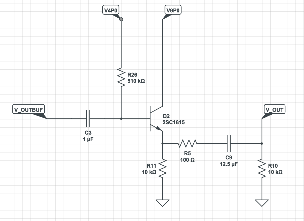
Output Buffer Circuit
###Tone Setting/Volume Level The tone/level stage is also just about identical to the Tube Screamer.
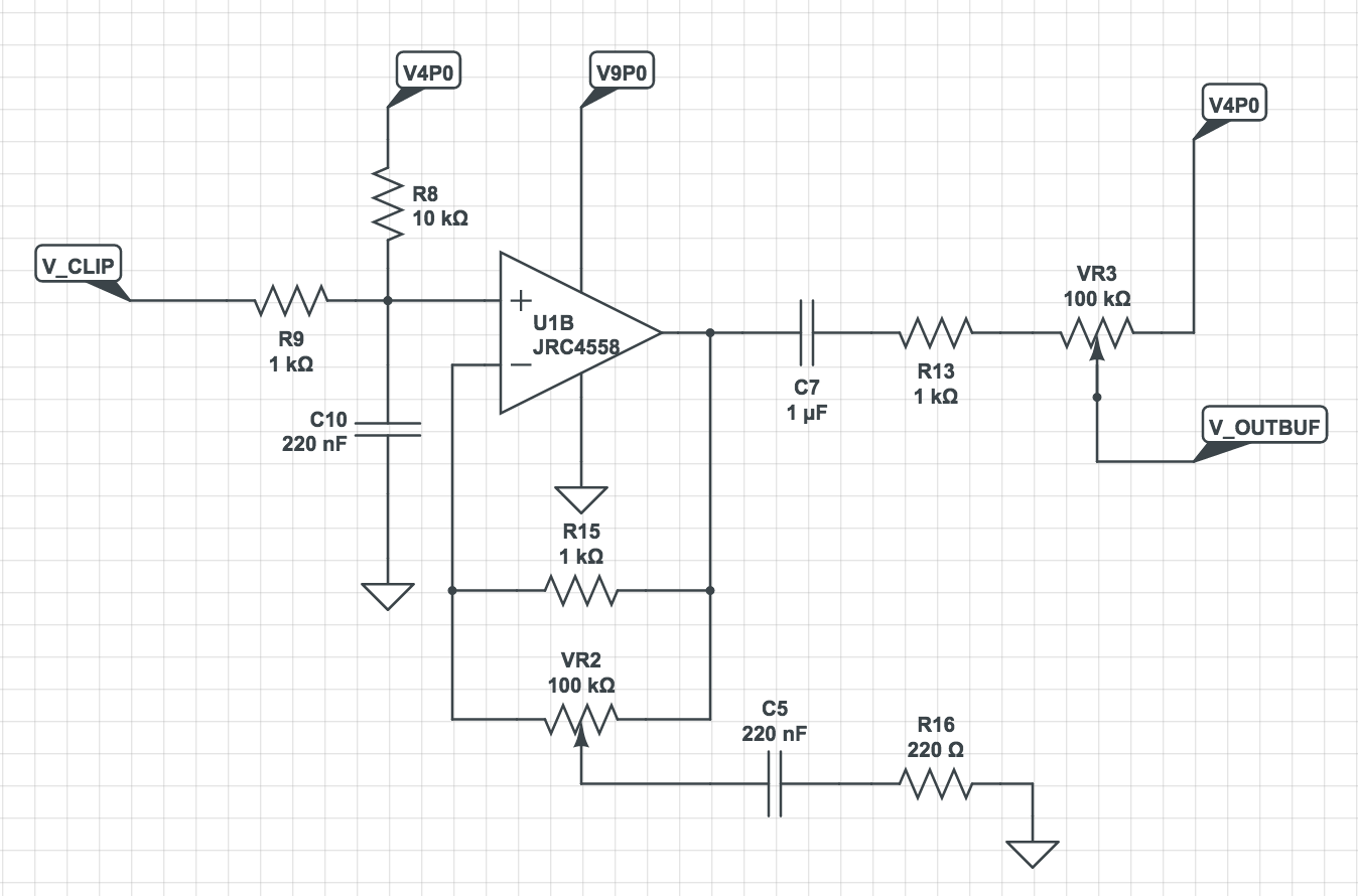
Tone Amplifier and Volume Pot
###Clipping Amplifier Donner really made this circuit their own is in the clipping stage. Note SW1 in the circuit block below. This is the toggle switch at the top of the PCBA allows the user to select “warm” or “hot” drive settings.

Clipping Stage
This allows the player to select the type of diode clipping they want. “Warm” selects the nominal Tube Screamer clipping stage of two back-to-back silicon signal diodes. I’m guessing these are 1N4148s, but since all I have to go by are appearance and turn-on voltage, I have no way of knowing for sure. The “Hot” setting switches out these diodes for a back-to-back pair of LEDs. The purpose of these clipping diodes is to limit the overall gain of the clipping stage. No matter the gain settings of the opamp feedback loop, the diodes ensure that the output of the clipping stage will never exceed the turn-on voltage of the diodes. Since LEDs conduct at a higher voltage than signal diodes, this has the downstream effect of higher overall gain across the frequency spectrum of your signal. Hence, flipping the switch to “hot” will give you a more aggressive, distorted guitar sound.
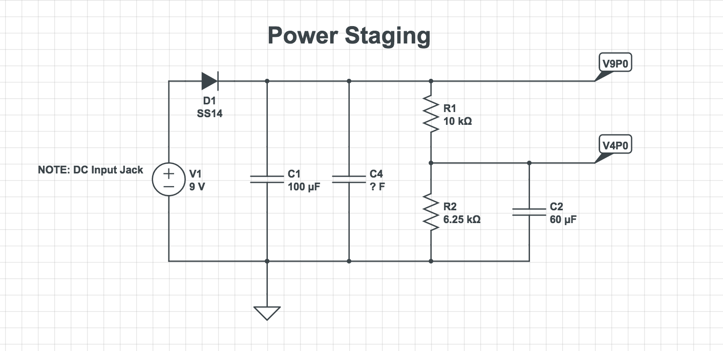
Power Distribution
Just for completeness’s sake, I included a quick ohm out of the power distribution section. You could likely introduce some interesting effects by tweaking these voltages, and by extension, the input/output buffer bias.
Power Staging
##A Few Mod Ideas
Changing the diode clipping is a pretty common suggestion in Tube Screamer modification pages. The toggle switch S2 is a ready-made platform to experiment with different clipping elements. By removing LED1 and LED2, you can wire in whatever components you like into the clipping opamp’s feedback path. Even better, you can do all of this while being able to go back to a stock TS808 clipping stage with the flick of a switch. As long as you don’t damage D2 or D3, you’ll have a stock Tube Screamer that’s an ideal piggyback for your own Frankenstein’ed creations.
Another simple mod is added low-end bass by modifying the value of C8, the pulldown cap on the feedback clipping path. C8 and R14 work to limit the frequency of clipping to those above ~720Hz. Increasing that cap value decreases the frequency cutoff. A 1uF 0402 capacitor in place of C8 is the simplest way to accomplish this, and drops the frequency cutoff point to about half of the original. You could also consider adding a switch that puts a second 0.047uF cap in parallel with C8. This is the more difficult option, as you’d either have to drill through the aluminum casing to mount the switch, or deal with it being buried inside the pedal. The upside is being able to switch between stock and modified bass responses.
Got any other cool mod ideas for the Tube Screamer? Drop me a line on Twitter to share!
##Acknowledgements LTSpice is great for building circuit models, but not so hot for simple schematic capture. To that end, I used a browswer based product called CircuitLab. They offer a totally cloud based solution for circuit analysis and schematic capture. Check ‘em out at www.circuitlab.com!